How to Read and Create Building Design Drawings Without Losing Your Mind
How to Read and Create Building Design Drawings Without Losing Your Mind
What Is an Architecture Plan Drawing (and Why It Matters for Your Renovation)
An architecture plan drawing is a scaled, technical representation of a building — or part of a building — used to communicate design ideas, guide construction, and satisfy permit requirements.
If you’re planning a renovation and just want the quick picture, here’s what you need to know:
The most common types of architectural drawings:
- Floor plan — A top-down view showing room layout, walls, doors, and windows
- Elevation — A straight-on view of an exterior or interior wall
- Section — A vertical slice through the building showing interior relationships
- Site plan — Shows the building’s position on the property
- Detail drawing — A zoomed-in view of a specific construction junction or element
What each drawing is used for:
| Drawing Type | Main Purpose |
|---|---|
| Floor plan | Space planning, permit applications |
| Elevation | Exterior appearance, facade materials |
| Section | Interior heights, structural layers |
| Site plan | Zoning compliance, setbacks |
| Detail drawing | Contractor construction guidance |
Here’s the thing most homeowners don’t realize: a single renovation project can involve dozens of drawings — each serving a different audience and purpose.
The architect uses sketches to explore ideas. The contractor needs precise working drawings with written dimensions. The permit office wants drawings that prove code compliance. And you, as the homeowner, probably just want to understand what you’re looking at without needing a design degree.
That gap between “what drawings show” and “what homeowners understand” is exactly where renovation projects go sideways — missed expectations, costly changes mid-build, and permit delays.
This guide breaks it all down in plain language, so you can read, question, and confidently work with any set of drawings your design team puts in front of you.
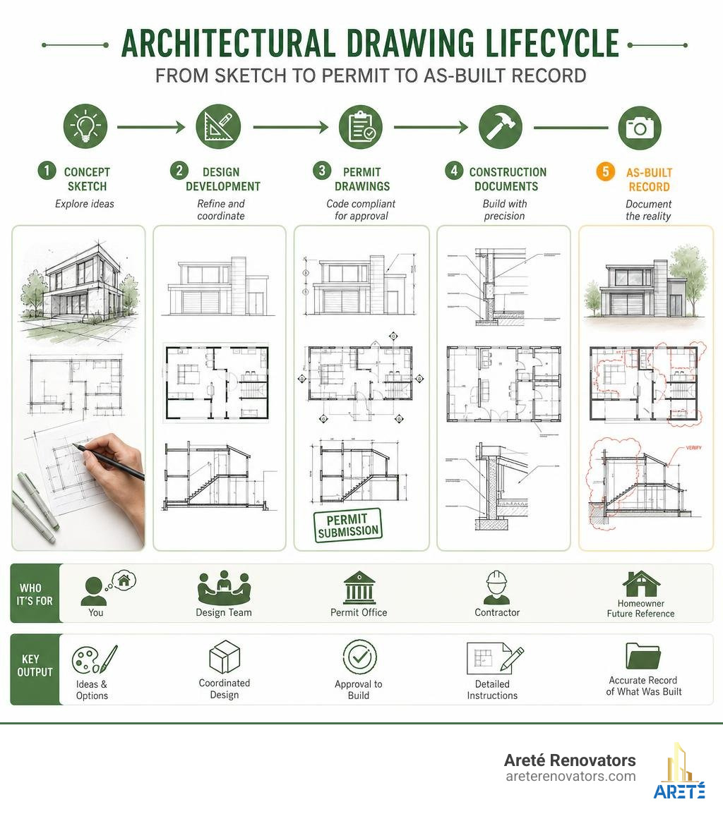
Demystifying the Architecture Plan Drawing: Types and What They Communicate
To understand how a building comes together, we first need to look at how architects translate three-dimensional realities into two-dimensional sheets. This technical translation is known as an Architectural drawing.
Historically, drawings were drafted by hand with ink on tracing paper. Today, in June 2026, we utilize highly sophisticated digital modeling, but the foundational drawing types remain the same.
The primary method used to represent a building is orthographic projection. This is a way of representing a 3D object in 2D by projecting parallel lines perpendicular to the drawing plane. Because there is no perspective distortion, orthographic drawings allow us to measure distances and scale directly off the page.
Within a standard project set, you will encounter several essential orthographic views:
- Site Plans: These show the entire property from a high-altitude bird’s-eye view. A site plan establishes where your home sits relative to property lines, neighboring structures, streets, and landscaping. For instance, in complex urban environments like Chicago’s Lakeshore East, site plans are crucial for understanding urban density and public space integration, as seen in landmark designs like The Park at Lakeshore East – OJB Landscape Architecture.
- Floor Plans: The absolute foundation of any interior remodel. A Floor plan is a horizontal slice taken through the building, showing how rooms connect to one another.
- Elevations: Flat, vertical views of the building’s walls, either looking at the outside of the house (exterior elevations) or looking directly at a wall inside a room (interior elevations, like a kitchen cabinet layout).
- Cross Sections: A vertical cut through the building, revealing the hidden layers of construction, ceiling heights, and floor-to-floor relationships.
To navigate a project successfully, it helps to understand that not all drawings are created equal. They are grouped into distinct categories based on their phase and ultimate purpose:
| Drawing Category | Primary Audience | What It Communicates | Key Characteristics |
|---|---|---|---|
| Presentation Drawings | Homeowners, Investors, Review Boards | Design intent, aesthetics, spatial flow, and material finishes | Often includes color, 3D renderings, furniture layouts, and realistic textures. |
| Working Drawings | Contractors, Subcontractors, Permit Reviewers | Technical construction details, structural requirements, and assembly instructions | Black-and-white, highly detailed, precise dimensions, material codes, and structural notes. |
| Survey Drawings | Architects, Civil Engineers, Zoning Officials | Precise existing property boundaries, topography, and utility locations | Created by professional land surveyors; critical for determining setbacks and legal building limits. |
| Record Drawings (As-Builts) | Homeowners, Future Architects, Facility Managers | The actual “as-constructed” reality of the building, reflecting field modifications | Documents any changes made during construction that differed from the original working drawings. |
When studying architectural drawings, looking at real-world examples can be incredibly educational. Curated directories like the Archello Architectural Drawings Guide, which contains 214,695 drawings and 394 featured drawings from buildings worldwide, show how diverse global design styles translate onto paper.
Floor Plans, Elevations, and Sections
To read a floor plan correctly, imagine taking a giant horizontal saw and slicing through a house approximately 4 feet (or 1.2 meters) above the finished floor level. You lift the top half off and look straight down. This specific height is chosen because it cuts directly through windows, doors, and major openings, allowing the drawing to show exactly where natural light enters and how people move through the space.
If you look at a standard Modern Style House Plan – 3 Beds 3.5 Baths 1845 Sq/Ft Plan #484-2 – Eplans.com, you will see this horizontal cut in action, clearly defining the spatial arrangement of the 1,845 square feet of living space, including the bedrooms, bathrooms, and garage layout.
An elevation, on the other hand, does not cut through the building. It represents the exterior facade or an interior wall surface from a straight-on, perpendicular perspective. Elevations are essential for visualizing vertical heights, window placements, and siding materials.
When we need to see what is happening inside the walls, we use a cross section. Think of a cross section as a vertical slice through the home. This view is indispensable for understanding structural framing, insulation layers, foundation depths, and how different floor levels align.
Presentation vs. Working, Survey, and Record Drawings
While a presentation drawing is designed to make you fall in love with a concept, a working drawing is what actually gets it built. Presentation drawings might feature beautiful furniture arrangements, shadows, and color-rendered materials to help you visualize your future life in the space.
Once you approve the design, we transition into creating working drawings. These are the highly technical blueprints that form the legal contract between you and your contractor, and they are the exact documents submitted to local building departments for permit approval.
Before any of these plans can be drawn, we must rely on survey drawings to establish the physical boundaries of your lot. And finally, once construction is complete, we compile record drawings (commonly called “as-builts”). Because real-world construction often requires minor field adjustments due to unexpected site conditions, record drawings document the exact final state of your home.
For those interested in the deep history of how these technical documents have evolved, archives like the Architectural Drawings and Records – Chicago History Museum preserve centuries of local building records, showcasing how Chicago’s architectural heritage was meticulously planned on paper.
The Anatomy of a Blueprint: Standards, Symbols, and Conventions

At first glance, a technical architecture plan drawing can look like a confusing web of lines, circles, and abbreviations. However, once you learn the basic visual language, reading them is as straightforward as reading a map.
One of the most important concepts to master is line weight (the thickness and darkness of lines). In architectural drafting, different line weights communicate different structural realities:
- Thick, Bold Lines: Indicate cut elements. In a floor plan, the thickest lines represent structural walls that have been sliced through.
- Medium Lines: Represent non-structural, fixed elements that are below the cut line, such as countertops, plumbing fixtures, and stairs.
- Thin Lines: Used for hidden lines, door swings, furniture, overhead elements (represented by dashed lines), and dimension lines.
Understanding these visual hierarchies is key to preventing mistakes. Historically, these conventions were printed on classic blue-toned paper. While modern printers use standard white paper, some teams still export layout files in a nostalgic blueprint aesthetic.
As discussed in the Export plan view as image format (to create ‘bluep… – Graphisoft Community, architects can easily set up layout templates with custom graphic overrides, utilizing dark blue fills and crisp white pens to export clean, blueprint-style raster or PDF images directly from their design software.
How to Read an Architecture Plan Drawing
When you look at a floor plan, start by orienting yourself with the north arrow, which tells you how the home is positioned relative to daily sunlight. Next, look for the following common symbols:
- Wall Thickness: Double solid lines indicate walls. Thick exterior walls usually show structural framing and insulation layers, while thinner interior lines represent partition walls.
- Door Swings: Doors are represented by a straight line (the door itself) and a thin, curved arc. This arc shows the direction the door swings, which is critical for planning furniture placement and ensuring walkways remain unobstructed.
- Window Symbols: Usually represented by thin parallel lines embedded within the thicker wall lines.
- Stairways: Shown as a series of parallel steps with an arrow indicating whether the stairs go “UP” or “DN” (Down) from that level.
Choosing Scale, Sheet Size, and Line Weights
Because we cannot print a house at its actual size, every architectural drawing is scaled down. To ensure these drawings are practical to transport and read on-site, they are printed on standardized paper sizes.
The most common large-format paper sizes are ISO A0 (841 mm × 1,189 mm) and Arch E (762 mm × 1,067 mm).
When choosing a scale, we must balance the size of the paper with the level of detail required:
- 1:100 or 1:96 (1/8″ = 1′-0″): Ideal for overall site plans and massive commercial layouts.
- 1:50 or 1:48 (1/4″ = 1′-0″): The industry standard for residential floor plans, elevations, and sections. This scale fits nicely on standard sheets while showing clear room divisions.
- 1:20 or 1:24 (1/2″ = 1′-0″): Used for detailed kitchen layouts, bathroom elevations, and built-in cabinetry.
- 1:10, 1:5, or Full Size: Reserved for highly specific detail drawings, such as window sill junctions, custom molding profiles, or waterproofing details.
Managing Complex Projects: Constructs, Views, and Collaboration

On a large-scale home renovation or custom build, a single drawing file simply isn’t enough. Managing a project requires coordinating architectural layouts, structural engineering, plumbing runs, and electrical grids. To prevent chaos, professional teams use structured drawing management systems.
For an in-depth technical breakdown of how these multi-file projects are structured digitally, Autodesk’s guide About Concepts of Drawing Management details how modern CAD and BIM platforms organize files into a centralized, logical hierarchy.
The Framework of Drawing Management Systems
Modern drawing management structures a project into three distinct levels, typically backed by an organized XML database:
- Constructs: These are the raw building blocks of the project. A construct represents a unique physical portion of the building (such as the first-floor structural shell, the core plumbing stack, or the roof framing) assigned to a specific level and division.
- Views: Once the constructs are built, they are referenced into “View” drawings. In a view file, we can combine multiple constructs (for example, overlaying the first-floor interior construct with the electrical layout) to add annotations, dimensions, and callouts without cluttering the raw building files.
- Sheets: Sheets represent the actual paper pages that will be printed or exported as PDFs. You simply drag and drop your annotated views onto a sheet template, which automatically handles title blocks, page numbering, and scale legends.
Balancing Aesthetics, Regulations, and Local Permits
Creating a beautiful design is only half the battle; the drawings must also prove to local authorities that the proposed work is safe and legal. Every municipality has strict zoning laws (governing building heights, property setbacks, and lot coverage) and building codes (governing structural safety, fire separation, and energy efficiency).
If you are planning an expansion, studying a comprehensive guide like A Contractor’s Guide to Home Additions and mastering the fundamentals of Home Addition Design will help you understand how these zoning and structural parameters dictate what can legally be drawn and built on your lot.
In the Chicagoland area, building codes and permit processes vary significantly by municipality:
- Chicago: Renovation plans must navigate strict Chicago-specific building codes. Depending on the scale of your project, plans may go through the Standard Plan Review (SPR) or, if working with an eligible registered professional, the expedited Self-Certification (SC) program.
- Evanston: Projects must align with local zoning ordinances that protect historic neighborhood character. Working with design professionals familiar with local standards, such as Architects Evanston IL | Hazlett Architecture Firm, ensures your drawings comply with local historic district guidelines.
- Highland Park: North Shore communities often have strict lot-coverage limits and architectural review processes. Collaborating with experts like Architects Highland Park IL | Hazlett Architecture Firm helps streamline the preparation of drawings that meet these precise suburban guidelines.
Additionally, when managing building plans in Illinois, public institutions and private entities must adhere to strict security and distribution guidelines, such as the Distribution of Building Plan Documents and Architectural Drawings policy, which limits the distribution of sensitive structural plans to protect building security.
From Ink to AI: How Technology Shapes Modern Drafting
The architectural industry has come a long way from the days of parallel rulers, drafting dots, and electric erasers. Today, the creation of an architecture plan drawing is powered by cutting-edge digital platforms that make design faster, more precise, and highly collaborative.
At Areté Renovators, we utilize these modern drafting advances to streamline our Architectural Drawings Design services, ensuring that your home designs are not only beautiful but technically flawless before construction even begins.
The Digital Evolution of the Architecture Plan Drawing
The technological evolution of drafting can be broken down into three major eras:
- Computer-Aided Design (CAD): The first digital shift, which replaced physical drafting boards with digital lines, arcs, and circles. While CAD made editing infinitely easier, the drawings remained flat, 2D representations.
- Building Information Modeling (BIM): A shift where we no longer draw flat lines; instead, we build a virtual 3D model of the home using “smart objects.” When we place a window in a BIM model, the software knows its dimensions, materials, thermal properties, and cost, and automatically updates every floor plan, elevation, and section instantly.
- Parametric Design: Allows designers to input specific parameters (such as structural load limits, daylighting goals, or material boundaries) and lets algorithms generate complex, optimized geometric forms that would be nearly impossible to draft manually.
Emerging Tech: VR, AI-Assisted CAD, and Cloud Collaboration
Today, the digital drafting space is evolving rapidly with cloud-native and AI-assisted tools:
- Virtual Reality (VR): We can now port our 3D design models directly into VR headsets, allowing you to walk through your kitchen remodel and experience the spatial scale before a single wall is demolished.
- SmartDraw: Used by over 85% of Fortune 500 companies, this accessible platform allows teams to quickly generate clean, professional diagrammatic layouts and floor plans using pre-built templates and vast symbol libraries.
- Rayon: This modern, web-based CAD tool has taken the design world by storm, allowing users to work 2 to 3 times faster than with legacy software. Rayon bridges the gap between complex CAD drafting and approachable, real-time multiplayer editing (think Google Docs, but for floor plans). It has become so popular that its “Urban Loft” template has over 3.6k users, its “Tiny House” template has 2.3k users, and it provides instant access to more than 4,000 architectural elements in its shared libraries.
Frequently Asked Questions about Architectural Drawings
Do I need a licensed architect for a home renovation?
In Illinois, the law requires construction documents for major structural changes, commercial spaces, or multi-family buildings to be prepared, signed, and stamped by an Illinois-licensed architect or structural engineer. However, for simple interior remodeling projects that do not involve structural modifications, a licensed general contractor can often prepare the necessary working drawings.
Additionally, the Chicago Department of Buildings offers a Homeowner Assistance Program, which allows owner-occupants of single-family homes to draft and submit their own plans for certain straightforward, non-structural renovation projects.
If you are trying to decide whether your project requires an architect or a structural engineer, check out our detailed Home Addition QA with Arete’s Architectural Associate Benjamin Wilson for professional insights on navigating design planning and local structural requirements.
What is the difference between an as-built drawing and a proposed plan?
An as-built drawing documents the existing physical reality of a building as it stands on-site today. A proposed plan, on the other hand, represents the future design intent — showing what the home will look like once construction is complete.
To see how these two drawing types work together during a remodel, you can review the Hayden Basement Project summary, which showcases side-by-side as-built layouts and proposed remodel plans for a complete basement renovation.
Why can’t I just scale dimensions directly off a printed drawing?
You should never scale measurements directly off a printed piece of paper. First, the printing process itself can introduce minor scaling errors; paper can stretch, shrink with humidity, or be slightly distorted by standard office printers. Second, the disclaimer “Do not scale off dimensions” is a standard legal protection on professional plans.
In real-world construction, written dimensions and specific notes always take precedence over physical scaled measurements. The general contractor is always responsible for performing on-site dimension verification before ordering materials or starting framing.
Conclusion
Understanding how to read and manage architectural drawings is the secret to a stress-free home renovation. When you can look at a floor plan, section, or elevation and clearly visualize the finished space, you eliminate the guesswork and ensure your design team, contractor, and permit reviewers are all aligned.
At Areté Renovators, we believe the design and construction process should be transparent, exciting, and completely seamless. By utilizing a highly structured, client-focused Design-Build Process, we coordinate every phase of your project under one roof.
From the initial sketches to the final stamped construction documents, our unified Design Build team handles all your Architectural Drawings Design needs. We provide you with a dedicated project coordinator and daily digital updates, so you always know exactly how your project is progressing.
Whether you are looking to remodel a historic single-family home in Evanston Architectural Drawings Design, update a classic residence in Highland Park Architectural Drawings Design, or renovate a high-rise condo in downtown Chicago, we are here to help.
Ready to bring your dream home to life on paper and in reality? Contact us today to schedule your design consultation.
